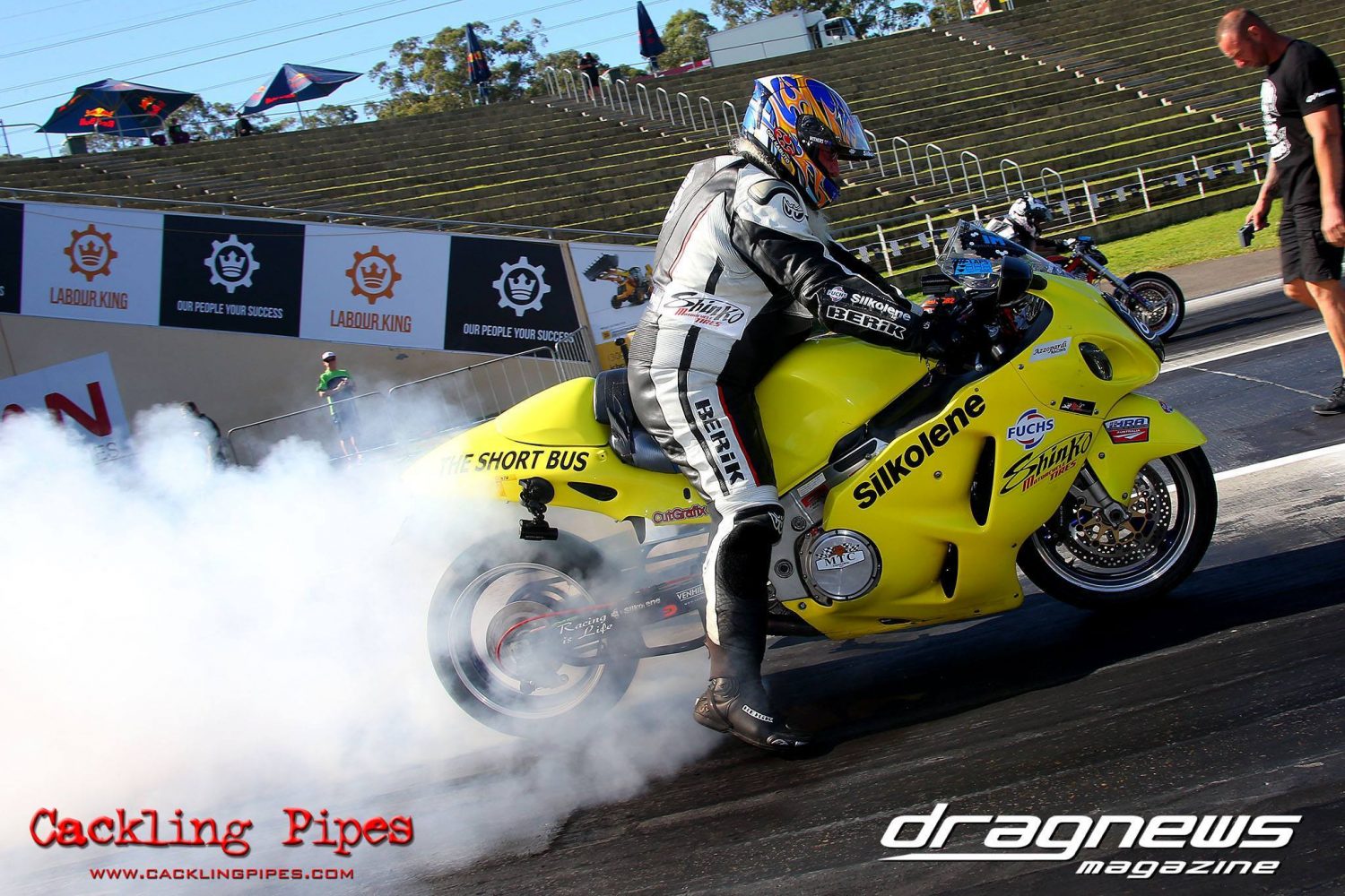
Mick Withers fits a MTC Slider Clutch to The Short Bus to find consistent reaction and sixty-foot times. Words & workshop photos: Mick Withers
After yet another early finish to a day’s racing due to inconsistent reaction times and equally sporadic sixty-foot times, the thought occurred that maybe it was time to search out a better way to do this.
In this case, ‘this’ was letting go of the clutch lever in a controlled and repeatable manner. Sounds easy, and it is if your fingers don’t open at random intervals. My problem is the middle finger on my left hand. Due to a condition called trigger finger, it doesn’t always straighten when told. Sometimes it opens like a factory finger, and then for no reason, it remains half-closed while the other three were fully extended. One day I’ll have surgery to correct it. One day.
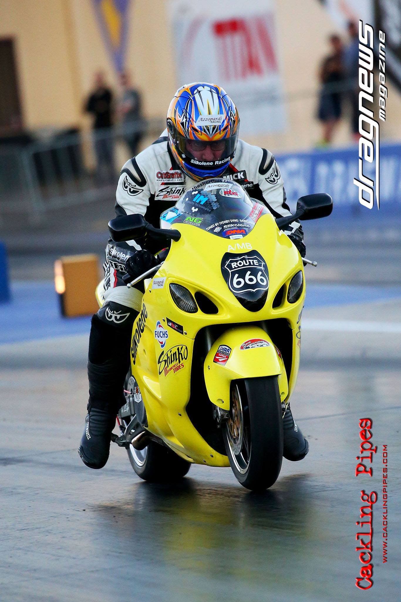
Image: Grant Stephens, CacklingPipes.com
The MTC Multistage Lockup clutch that was fitted to The Short Bus is a fine piece of engineering. Since being designed and developed by MTC, it has formed the basis for most of the aftermarket replica clutches being fitted to drag bikes all over the planet. Mine came second-hand from a racer in the US. It was complete and in brand-new condition. As soon as I saw it for sale, I was on it like a seagull on a hot chip. The price was good, the seller was honest and the deal was done.
Shortly after it landed, I had it modified by a mate so that I could change the dynamic springs quickly and easily. The dynamic springs are the ones that control the movement of the lockup arms.
The original method of changing these springs was painful and took a good 20 minutes along with the added opportunity to strip threads and drop small bolts.

My method was a direct copy of what MTC started offering on new Multistage Lockup clutches from 2012 onwards. I’m quite happy to recognise good ideas and adopt them. In reality, I haven’t changed those springs very often but when I have it’s been a quick and easy operation.
MTC started offering the Gen 2 Multistage in 2012. To a casual observer they probably look much the same but they have one major difference. The original Multistage Lockup was hub-driven and was completely reliant on rear wheel speed.
The Gen 2 is driven off the outer clutch basket and that is connected to the crankshaft. With the original, if you miss your clutch’s happy zone and it starts slipping, the rear wheel speed will not increase, the clutch throwout arms won’t apply clamping pressure to the clutch pack and you stand a good chance of destroying the clutch plates.
The Gen 2 differs in that you can have a bit of clutch slip and as the engine rpm increases, the arms will throw out and lock the clutch pack. A Gen 2 was considered but two things stopped me. The first was the need to still release a clutch lever, and the second was that to make a Gen 2 work in my application, I’d have to run minimal base spring pressure and riding it back to the pits after a run would seriously shorten clutch life.
In an attempt at making the clutch release less dependant on my gammy fingers, I fitted an electric linelock in the hydraulic clutch line. In simple terms, a linelock is an electric solenoid that holds line pressure in a hydraulic line while power is applied. Remove the electrical power and the solenoid releases the pressure.
In practice, it worked like this: Stop before the startline and squeeze the clutch lever; while holding the lever in, push the button in front of my left thumb and hold it while releasing the clutch lever. As long as I held the button, the clutch was engaged but as soon as I released the button, the clutch was also released.
Because I like doing things like this, I also had the two-step revlimiter activated by the same button and an eight-pole relay. The theory was great but getting the clutch release and soaring engine rpm to work together was easier to describe than control.
Looking at the datalogger, I could see that if I could hold engine rpm constant for a very short period of time after the release of the button, I could make it all work. After looking at an MSD SB6, I saw that it would do what I wanted. But MSD stopped making this unit due to falling sales.
Back to square one.
A quiet half-hour sitting in the shed brought forth an amazing memory from my days racing Harleys in P/CB in the 1990s. A thing called a slipper clutch: the world’s simplest motorcycle clutch. Turn the throttle and go. MTC were the originators and the slider clutches that they offer use the exact same principles as the originals.
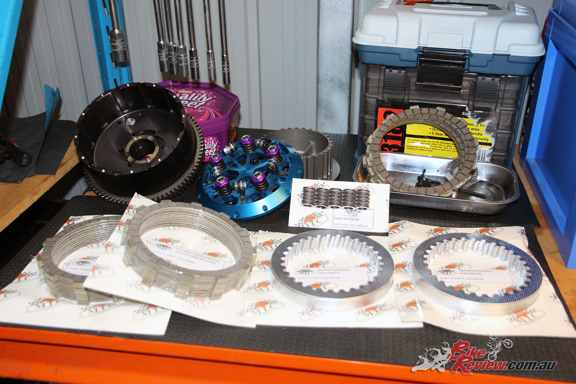
The box of happiness included an MTC Slider and spares including a couple of clutch packs.
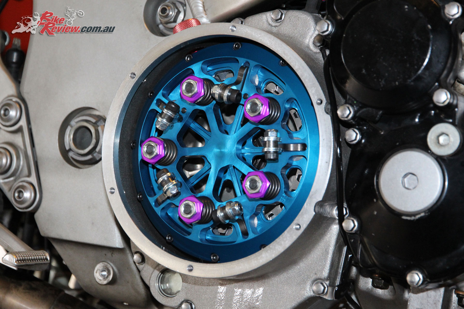
The outer hat and pressure plate of the slider clutch are held in contact by spring pressure. In the MTC Slider, five 8mm studs are locked into the pressure plate. They extend out through the hat and then five springs with locknuts are threaded onto those studs. The base of the springs press on the outer hat. Spring pressure resists the application of clamping pressure being applied by the throwout arms. Securing the MTC slider hat to the billet basket are 12 cap screws.
There’s no clutch lever for my fingers to hang on to. Twist and go.
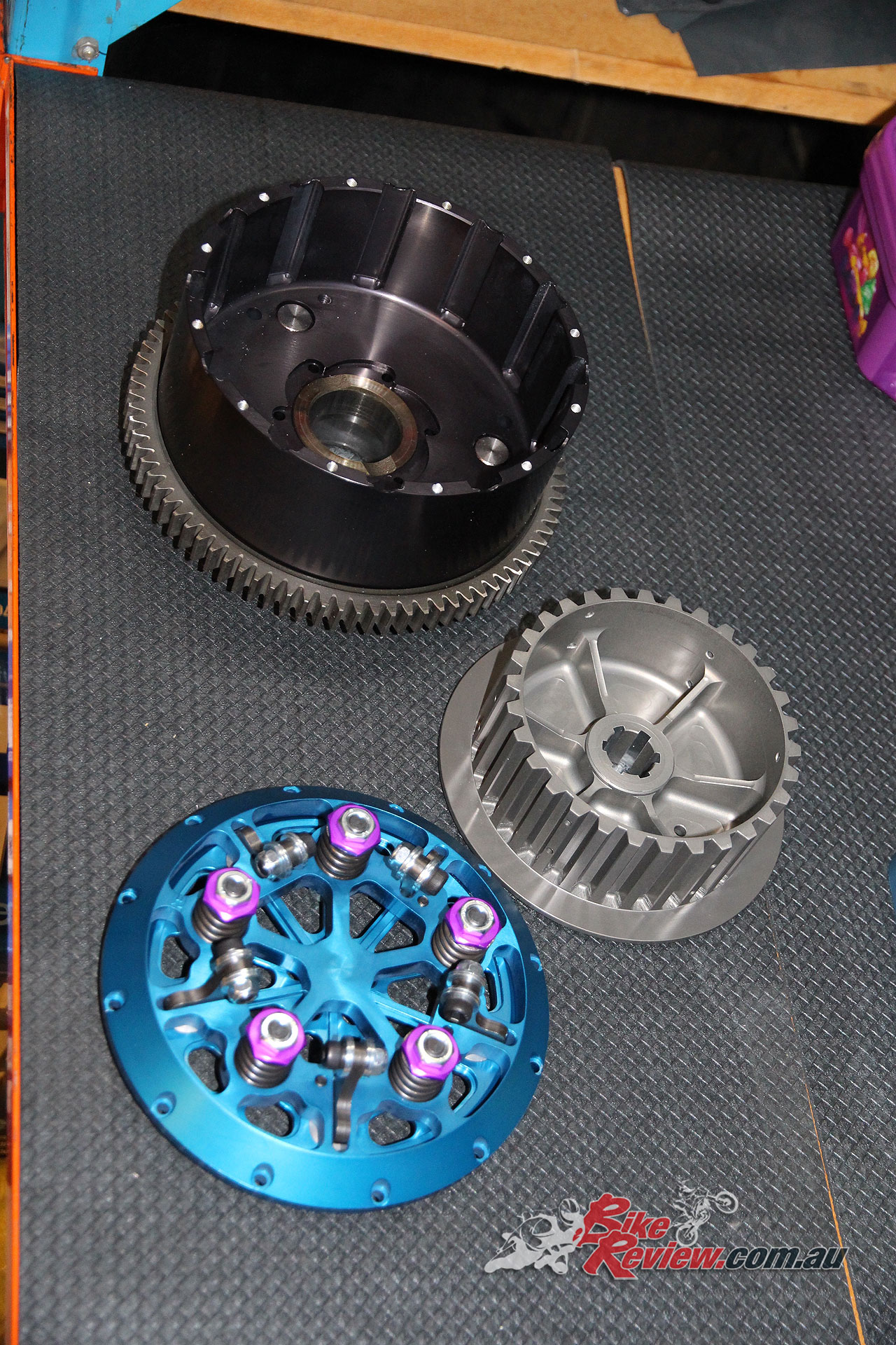
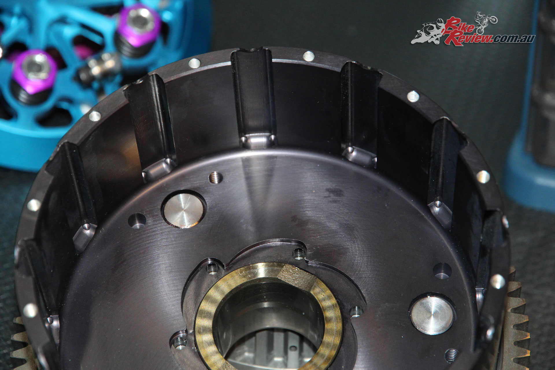
FROM THE TOP: Clutch basket, inner hub and slider hat and pressure plate. Anodised MTC billet goodness.
Simple in concept and almost as simple in design yet very well made in MTC’s in-house CNC machining centres. The outer basket is machined from a solid chunk of high-grade aluminium, as is the inner hub, pressure plate and outer hat. All of those components are anodised before shipping.
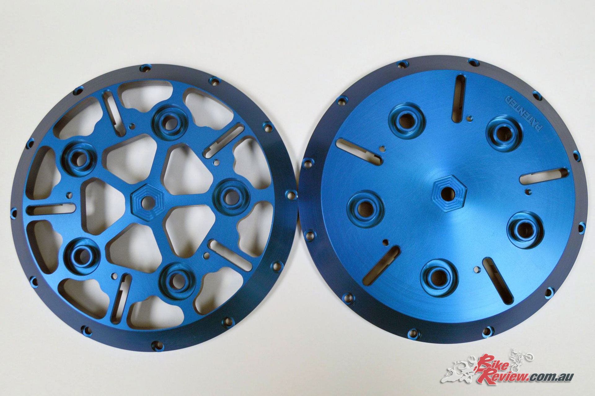
On the right is an original MTC slider clutch hat and on the left is a lightened version.
When I placed my order with Scott from Rapid Motion, the MTC dealer I chose for this particular exercise, he recommended that I also invest in MTC’s own clutch plates. I’ve had great success in the past with APE Trac King fibres but their steel plates weren’t as long-lived.
Scott had previously recommended the hard-chromed steels from MTC and I started using them. Instead of throwing warped steels away every couple of meetings, they lasted much longer. Based on that experience, two sets of MTC hard-chromed steel and fibre clutch plates were added to the order.
Starting the ball rolling, I sent my original Suzuki clutch basket over to MTC Engineering in Florida. The option was there to have them supply one at a reasonable cost but I already had one that I’ll never use again. The original basket is dismantled and the backing plate with drive gear is attached to the MTC billet outer basket.
Smart move. Suzuki spend a lot of time and effort making sure that their stock components fit and work well together. Makes perfect sense to re-use those parts.
Watching my parcel on USPS tracking was a joy until it hit Sydney Airport and disappeared into the depths of Customs. Because Scott from Rapid Motion is a friend, he’d organised for my Slider to be shipped direct to me from MTC. That meant that I was also liable for the customs clearances and fees. After submitting the relevant paperwork, and paying the 10% GST and a $90 clearance fee, my box of clutch happiness was finally delivered. A happy day.
After re-reading the seven steps of the MTC installation instructions, the MTC Multistage was quickly removed and packed away. There are no tricks to installing the MTC slider. You will need a 30mm socket for the clutch hub nut. I’ve got a cordless 18v Ryobi rattle gun and it made short work of the clutch hub nut. Because I’m a fussy-type of bloke, I used brand new genuine Suzuki clutch hub nut and washer. Less than $20, it’s cheap insurance.
Using digital depth gauge to measure clutch spring heights before installation.
With the outer basket and hub fitted, the end float on the basket had to be measured. MTC specify 3 to 6-thou, any less and the basket could start binding up on the hub when the hub nut is tightened. Any more than that and the excessive movement could cause other problems. Mine was right in the middle of the range. Cool. The oil restrictor plug was tapped into the end of the input shaft.
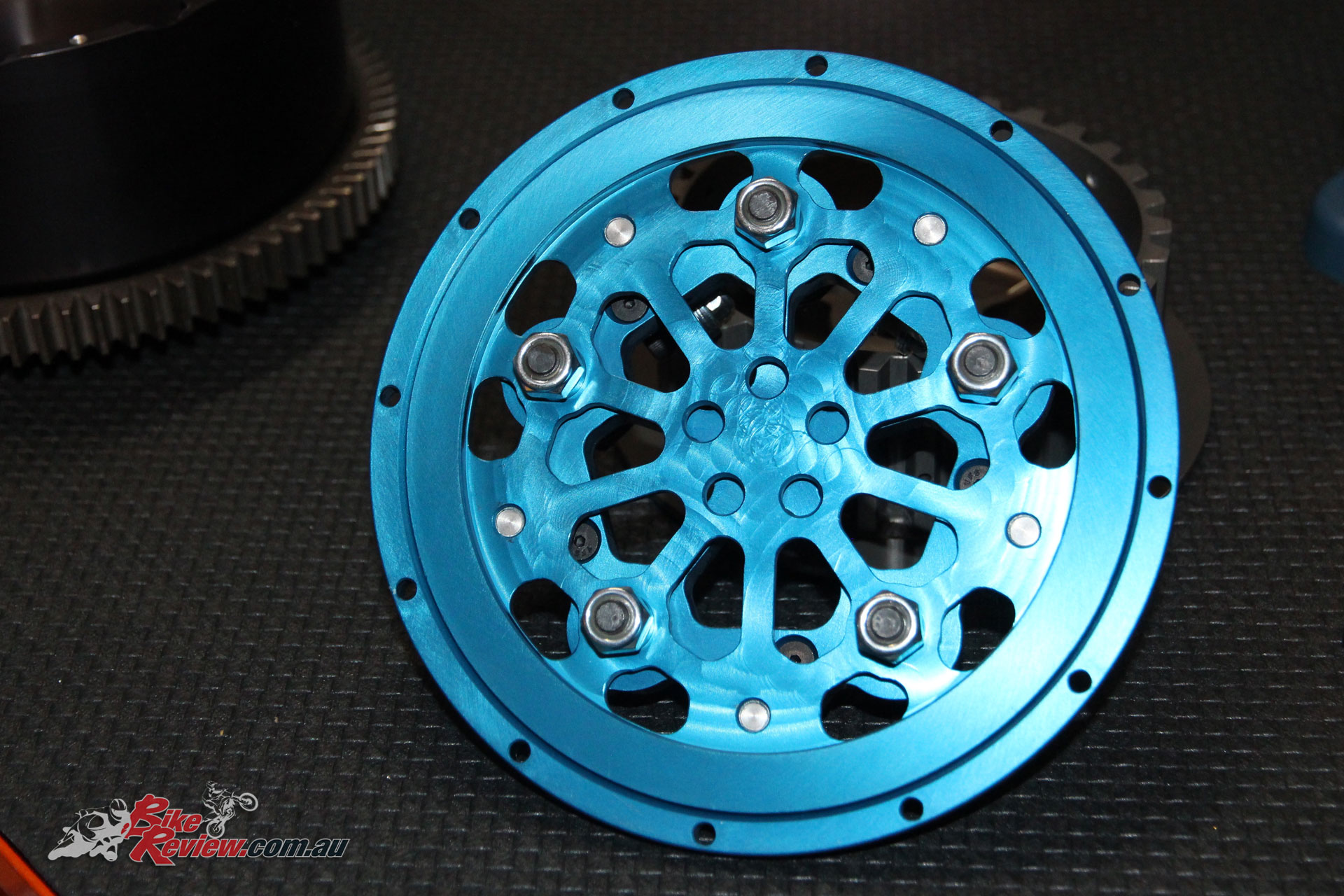
The clutch-side of the MTC slider pressure plate.
With all of the spinny bits tightened, it was time to measure the step on the clutch pressure plate. Right on .042”, I wrote that number on the bench with a texta before measuring the depth of the clutch basket and writing 1.992” next to the .042”. Simple maths was needed to work out the clutch stack height. MTC specify an airgap of .050”. So, 1.992 – .050 (airgap) makes it 1.942. Take .042 (step in pressure plate) away from that and the resultant 1.900 is the stack height I need. That works out at 48.26mm for you younger types.
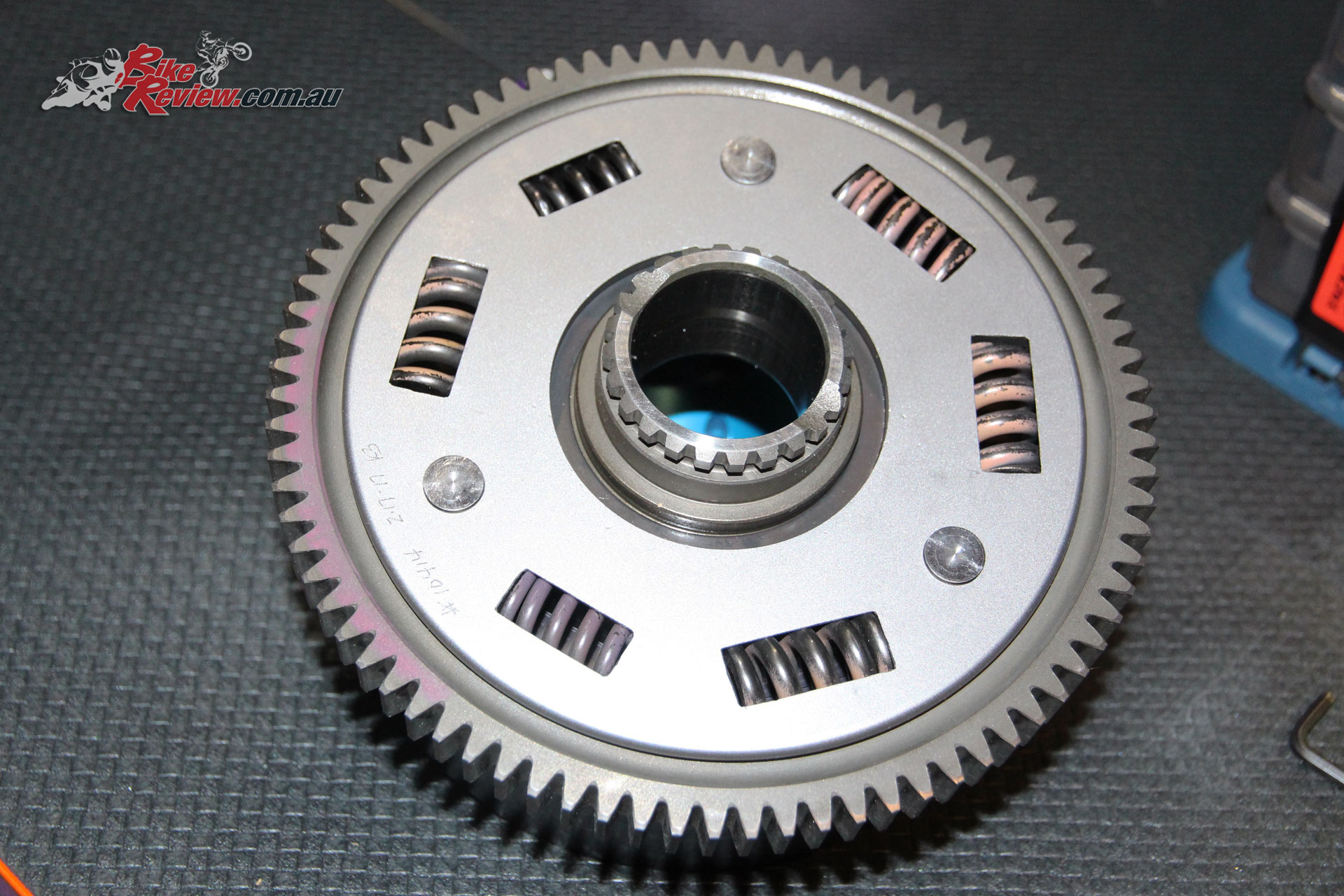
Original Suzuki drive gear. Fitted to MTC billet basket, complete with new springs.
Putting a clutch pack together that matched that stack height was easy with the new MTC plates and it was fitted, fibre first and last. There are people who swear by soaking the plates in oil for a day before you fit them. My method is to dunk each fibre plate in an ice cream container full of Silkolene Pro 4 XP before sliding it into the basket. Make your own decision. This works for me.
The machining is a thing of beauty.
Because I like to have spares of consumables, I also added a spare set of clutch springs to the order. There are three different spring packs available but I chose to stick with their standard fitment. They’ll give me the stall rpm that I want. Apparently the springs last for years, but I’ve got spares if they ever start to lose their tension.
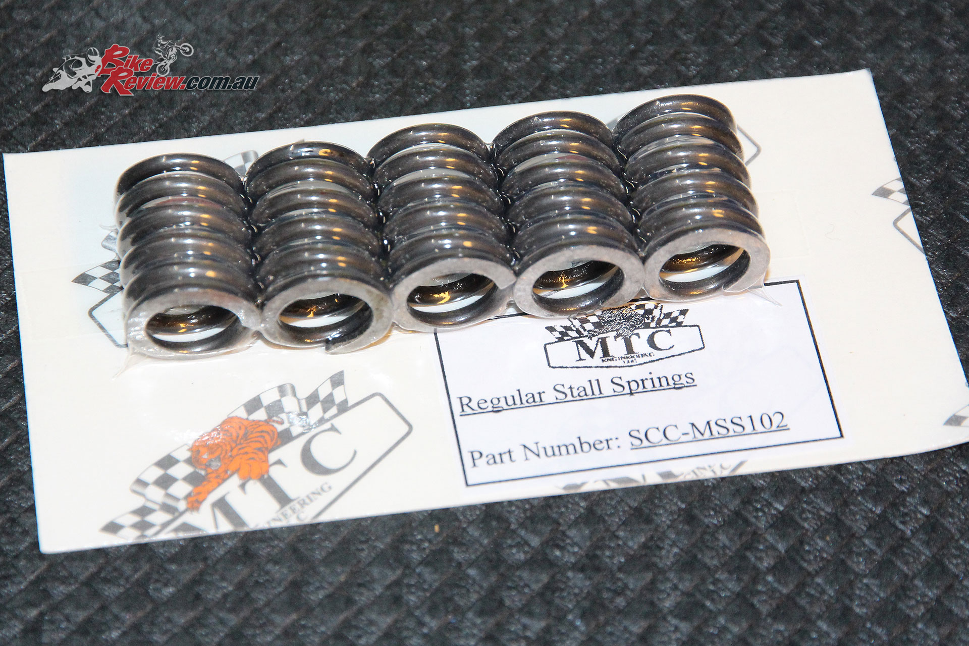
Spare regular stall springs.
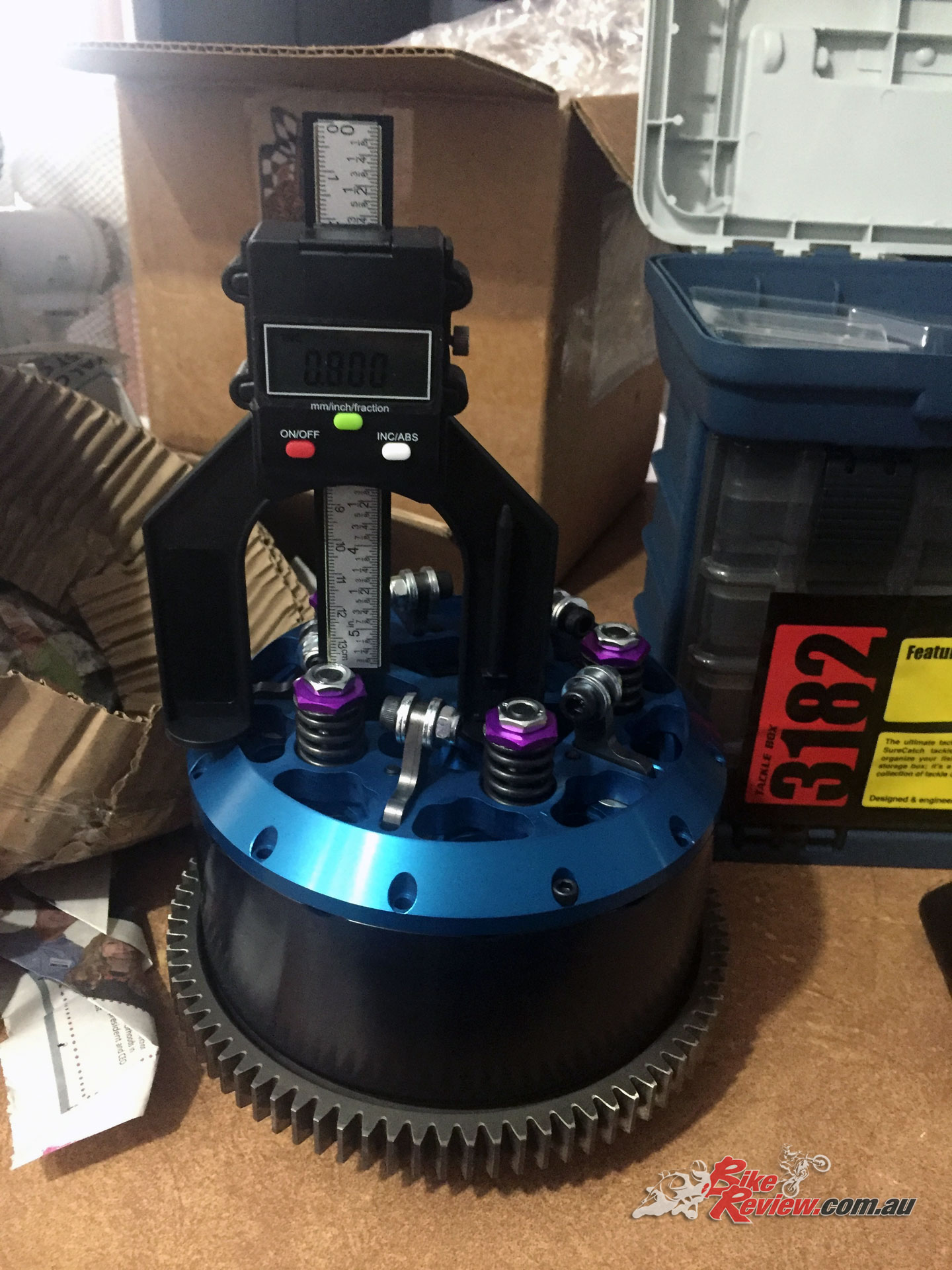
Increasing spring pressure increases the rpm required before the arms start to apply pressure. The standard springs are reportedly good up to 5500rpm in a Busa, so I’ve got plenty of margin before they’re going to coil-bind. I started off with .800” of spring height. This is a measurement from the surface of the clutch hat to the top of the purple nuts on top of the clutch springs. I’ve done this before and bought a digital depth gauge specifically for the job. Dial calipers are good but in my hands, not as accurate or repeatable.
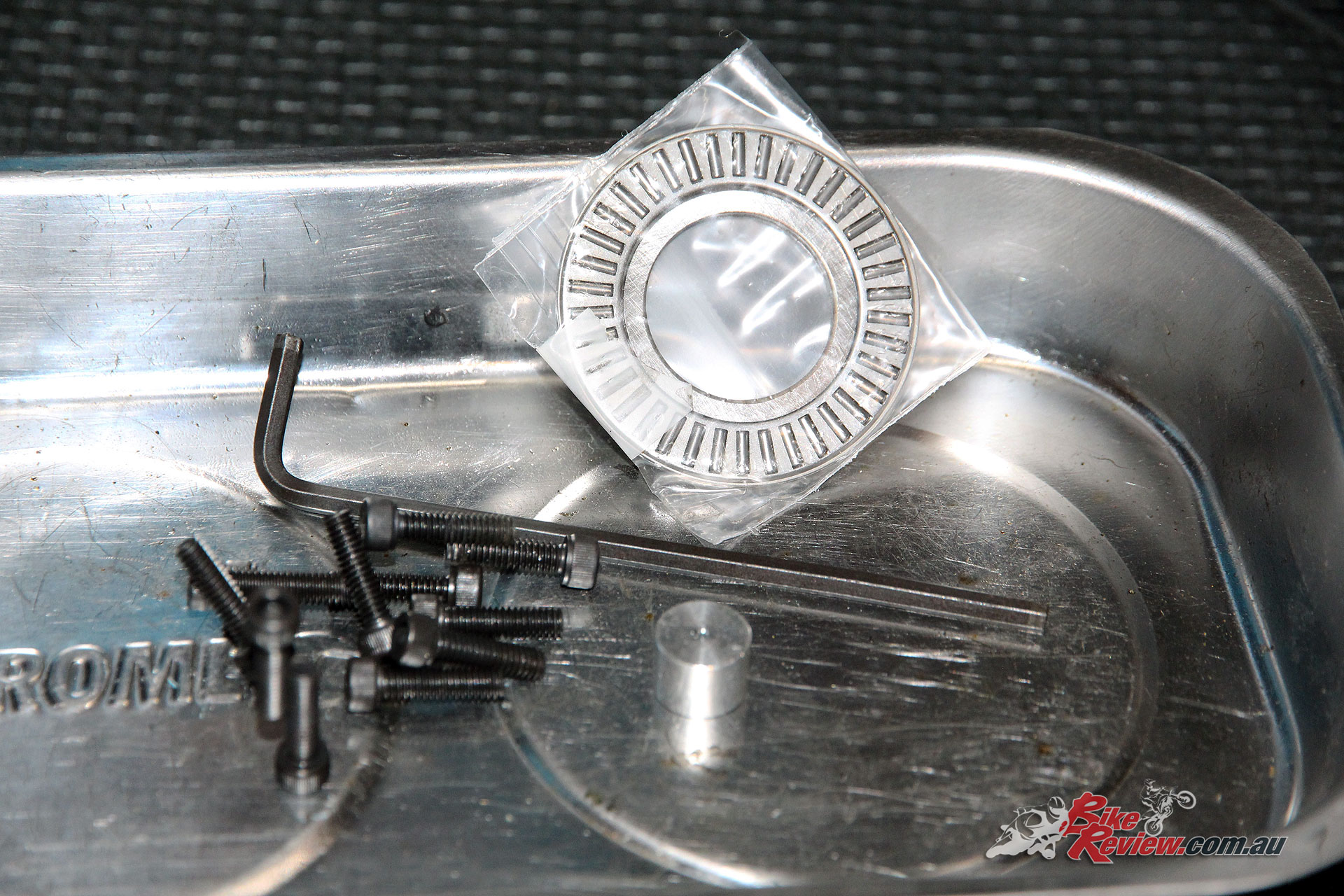
Oil restrictor plug in front of three-piece bearing.
As it arrived from MTC, the slider’s throwout arms were all carrying a nut, bolt and four washers. On my scales, they weighed in at 12.75g apiece. Based on the info I had at the time, I took two washers off each arm for my first pass.
The hat and pressure plate are held in place by a dozen little cap-screws that go through the hat and lock it to the outer rim of the clutch basket. Don’t over-tighten these screws (or leave them loose), or your day will quickly turn brown and smelly.
The last pic of the MTC Multistage before it was removed and packed away.
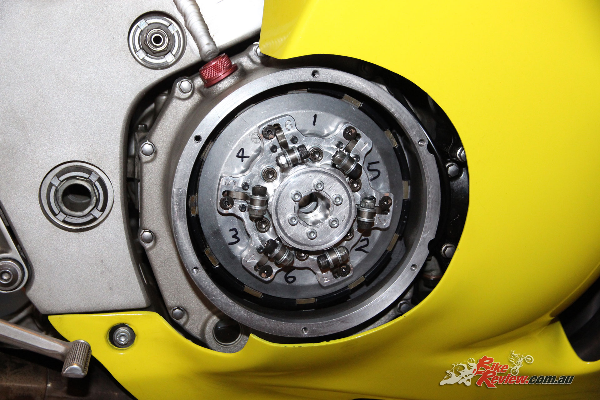
The Australian-made LAE quick-access clutch cover I fitted at the same time as the MTC Multistage Lockup clutch was perfect for use with the slider. So it’s still there. Undo six cap-screws and the o-ringed cover is off. With that off, the stall springs and the throwout arms are right there in front of you.
After checking that nothing was touching anything that it shouldn’t, the outer cover went on and it was time to fire the Short Bus up. A couple of quick shed-skids showed that the clutch was doing its thing. Happy days.
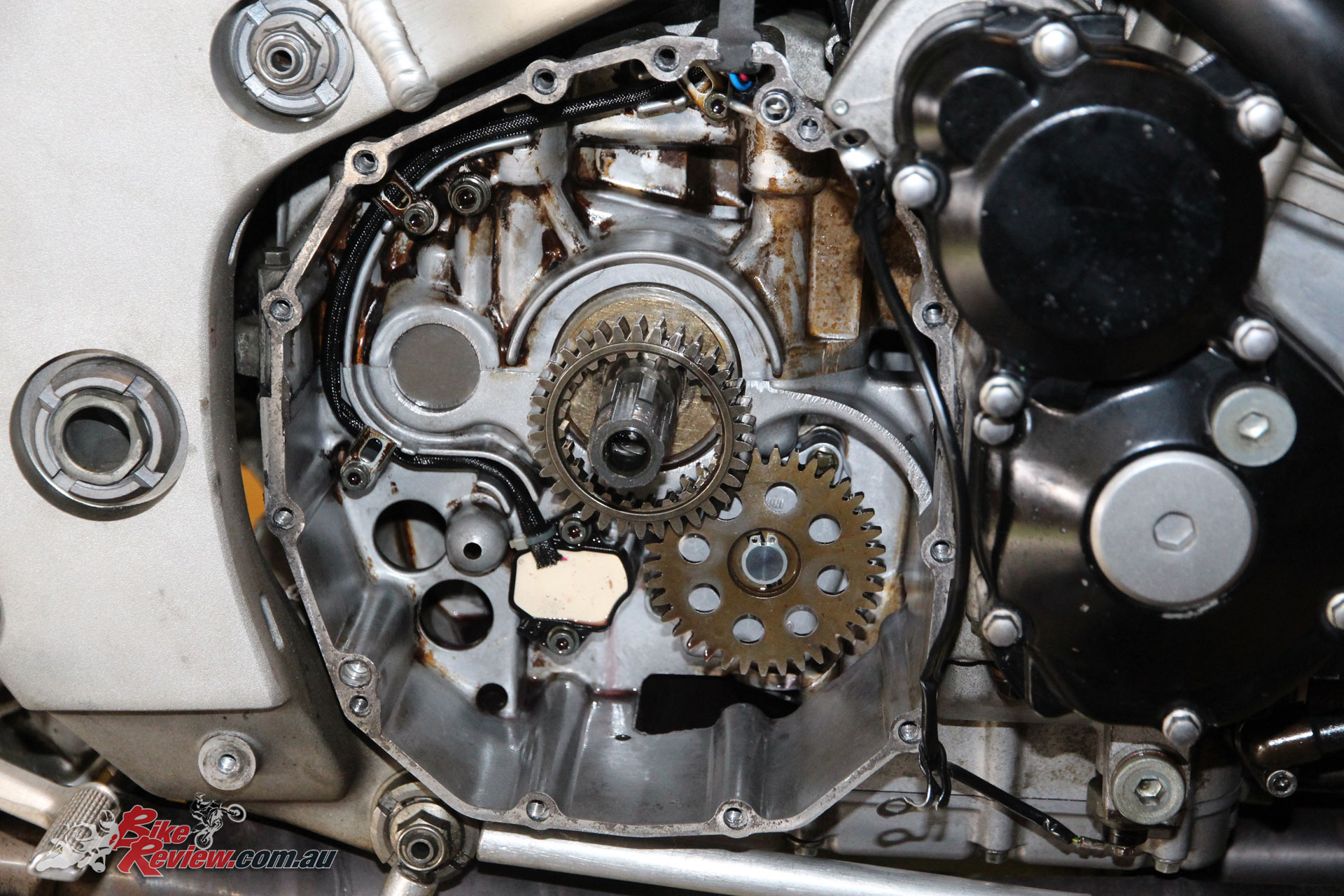
Clutch basket removed. Look carefully and you can still see evidence of an engine that has been overheated and run on old oil earlier in its 92,000km life.
With no need for a clutch lever, I decided to re-purpose the left-hand master cylinder to operate the rear brake. A new Venhill braided line was plumbed in from the linelock to the rear caliper. The clutch switch is still in place and operated by the rear brake lever, or the button under my left thumb. The same circuit controls the two-step rev limiter.
MTC recommend that the two-step be set 250 to 400rpm below the stall speed set by the clutch. This is the rpm where the bike tries to start driving away. For example, stall speed is 3400rpm, the two-step needs to be set at 3000 to 3150rpm. The standard Busa tacho is accurate within 500rpm so I plugged the laptop in and watched the on-screen tacho from the WEGO 3 to set the two-step.

Oil pump drive gear. Make sure you’ve got it facing the right way.
With all of this done, it was time to put theory into practice. The previous meeting was also my last with the MTC Multistage. Consistency? I could barely spell it that day. My 60-footers varied from 1.99 to 2.12 and the ETs were no better. It was not a good day. First meeting with the Slider and I was squeezing out little drops of brown adrenalin.
The first run was a 10.12 with a 1.72-second 60-foot. That was with just enough throttle to activate the two-step. I added another washer to each of the throwout arms and lifted the two-step 100rpm for a 10.01 with a 1.70 shot time.
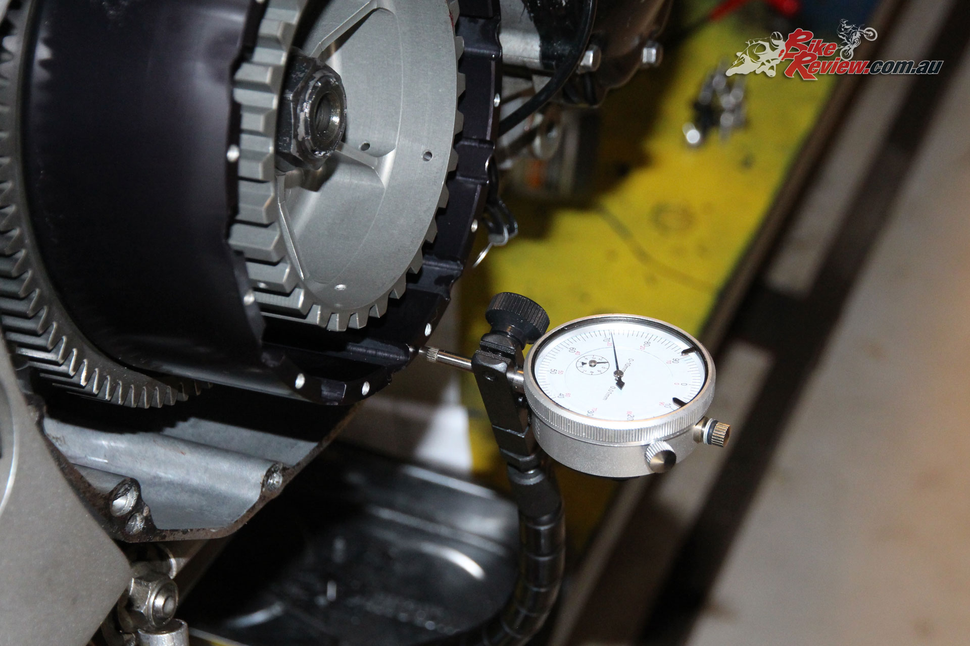
Dial gauge used to measure end float of clutch outer basket.
With a whisper more throttle, the third qualifier was a 9.85 with a 1.65 sixty-foot. In the first round, I redlighted but still ran 1.64 in the sixty and 10.00. You can’t really draw any solid conclusions from that meeting because I was tentative at best with the throttle but the indications were good.
A week later I was back and the first five passes netted a best of 9.85 with a slowest of 10.06. Again, I was tentative about leaving the line with the throttle wide open but decided to give it a go on the last pass of the day. With the throttle on the stop, I let go of the button and the front wheel started to climb straight away, so I squeezed the rear brake and rolled the throttle off. I know what the sky looks like from the seat of the Short Bus.
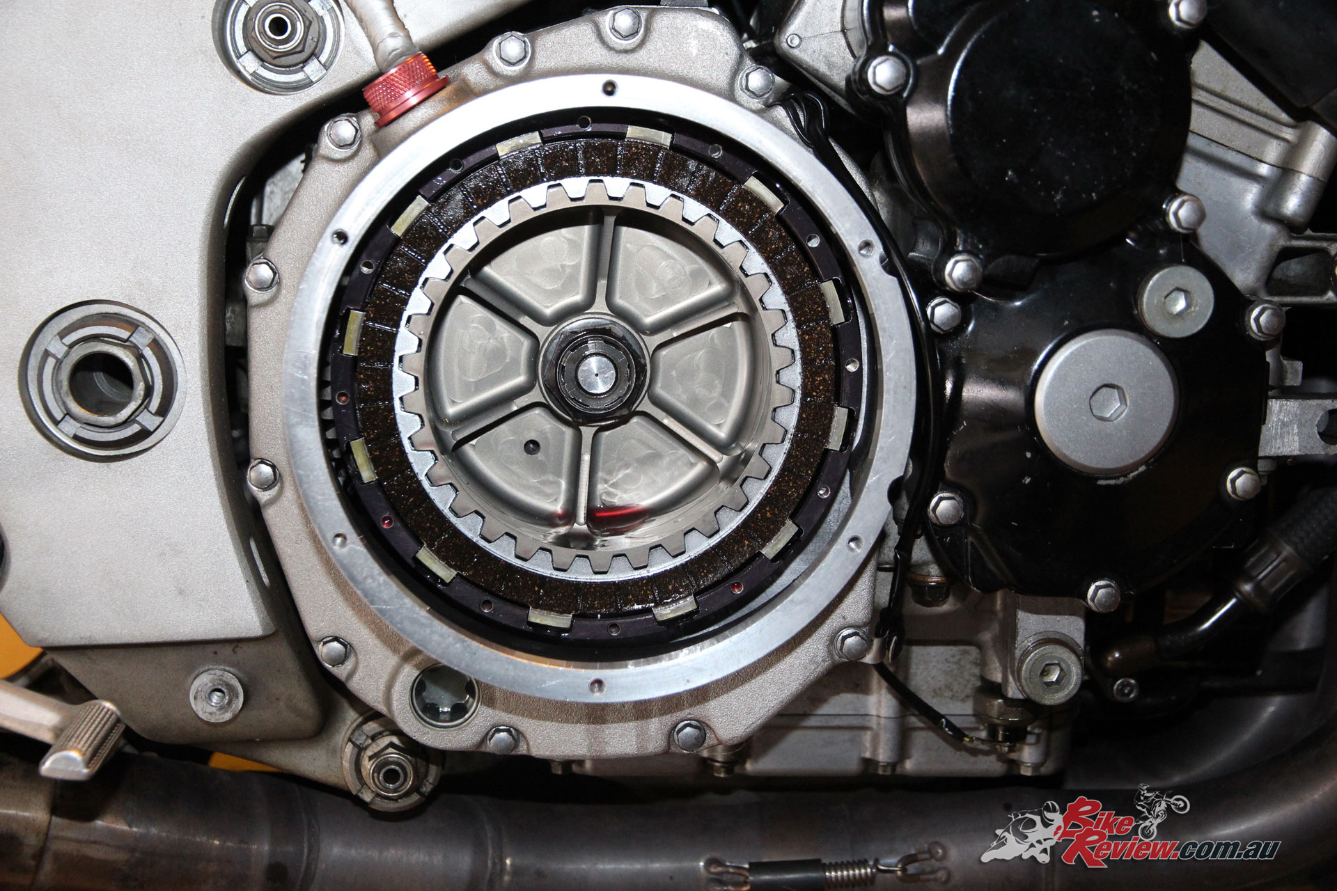
New clutch plates fitted after their dip in the Silkolene Pro 4 XP. Look carefully and you’ll see the oil restrictor plug in input shaft.
The next meeting was more of the same. I was sure that I was doing something wrong and that it was my fault that the front wheel was climbing.
Leonard from Azzopardi Racing is responsible for the Short Bus’s driveline. We spent a lot of time going back and forth with ideas on how to keep the nose down, mainly directed at suspension and chassis setup.
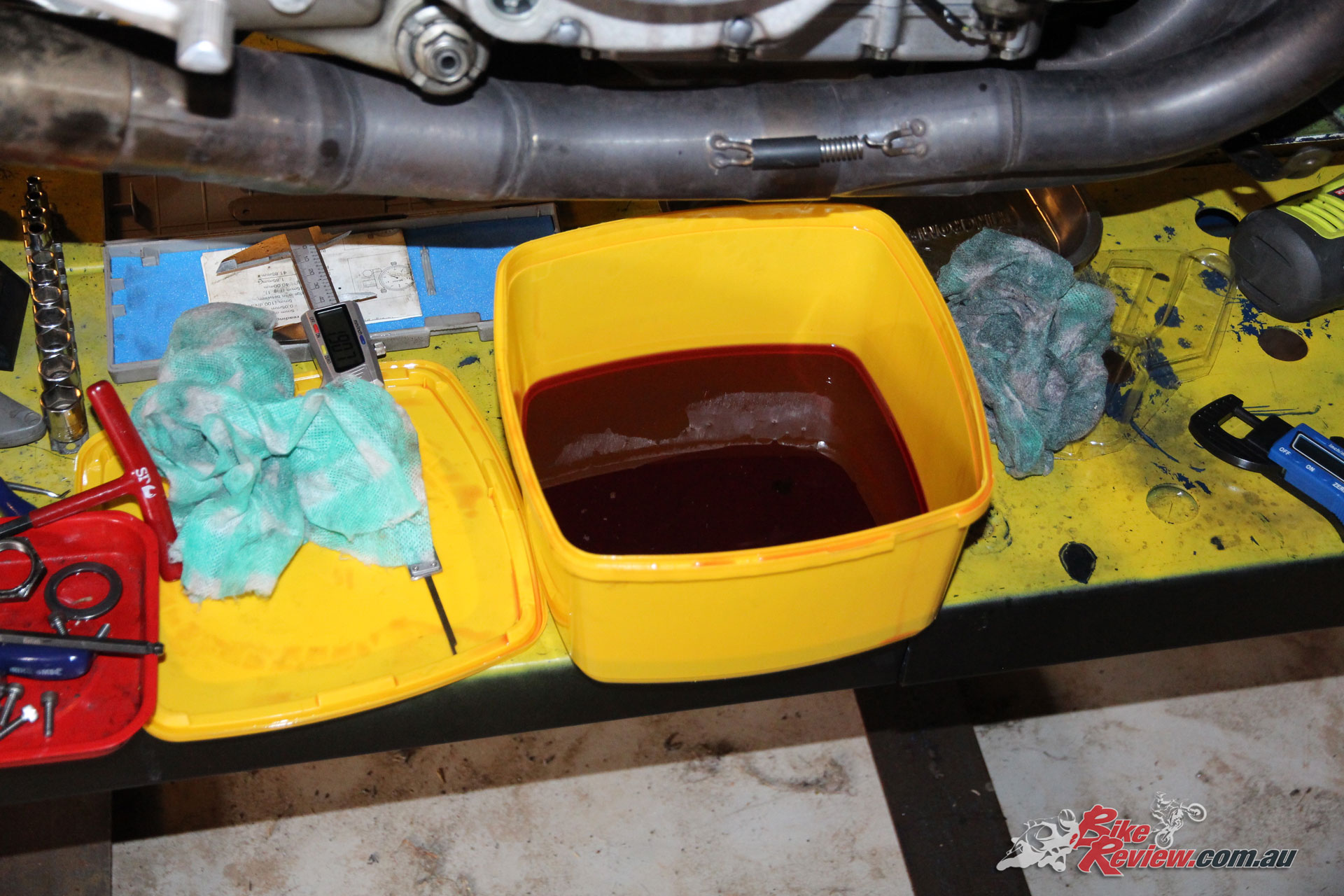
Silkolene Pro 4 XP dipping container.
The key ingredient we were missing was information. Neither of us had experience with a slider in a no-bar bike and we were looking at it with a combination of our combined and varied experiences. Then an old mate offered to help at Sydney Dragway’s Nitro Thunder meeting.
Ken Peatey is his name. He’s been around and owns Rascal Race Engines. Straight away he told me to add weight to all five throwout arms: A total of 40 per cent more weight than I’d been running. Last time I put more weight on was when it tried to wheelstand so I’d been pulling weight off in the hope that I was going the right way. I wasn’t.
MTC Slider ready for action.
With a brand-new Shinko Hook-Up on the back wheel and Ken’s heavy arms, the stall was 3500rpm and the two-step was on 3200. Complete with heart in throat, I let go of the button. The Short Bus felt very lazy off the line and I was disappointed. A time card showing a 1.57 sixty-footer and a 9.72 stopped that thought. With a bit more spring pressure, the stall increased and the two-step reset, I ran a 1.58 sixty-foot and a PB 9.599 on the next pass.
Ken looked at the data and suggested taking a washer off. We won’t mention the third qualifier because my head fell off and I rode like shit. But we will talk about the first round of eliminations. With no changes, I dialled up WOT and let go of the button. Everything seemed to go into slow motion, probably because of the adrenalin coursing through my system.
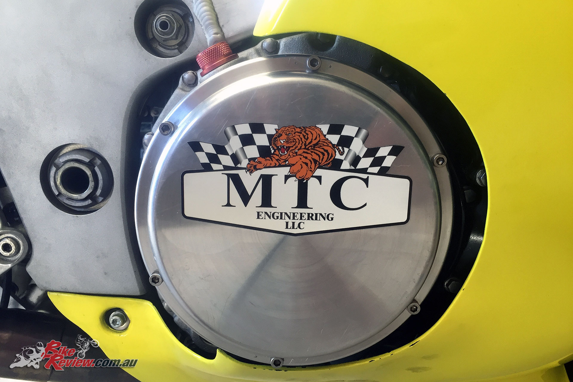
The final job was the new sticker on the LAE Quick Access clutch cover.
The shiftlight was taking forever and I shortshifted to second after deciding that the light must be broken. The light came on at the top of second, and did for each gear from then to the finish line. I was tucked in as tightly as a 140kg bloke can and crossed the finish line with a new PB of 9.535.
According to the timecard I lost but personally, I’d won. PBs and confidence will do that.
The missing ingredient: To keep the nose down, add weight to the throwout arms. If it’s not lifting, take a washer off at a time until it does and then back up a step. No one had told me that and I couldn’t find it written anywhere.
Keep notes. Write everything down. My runs from the Nitros show sixty-foots of 1.578, 1.584, and 1.557. Half-track numbers were 6.29, 6.19 and 6.13 with speeds of 115.88, 117.25, and 117.57mph.
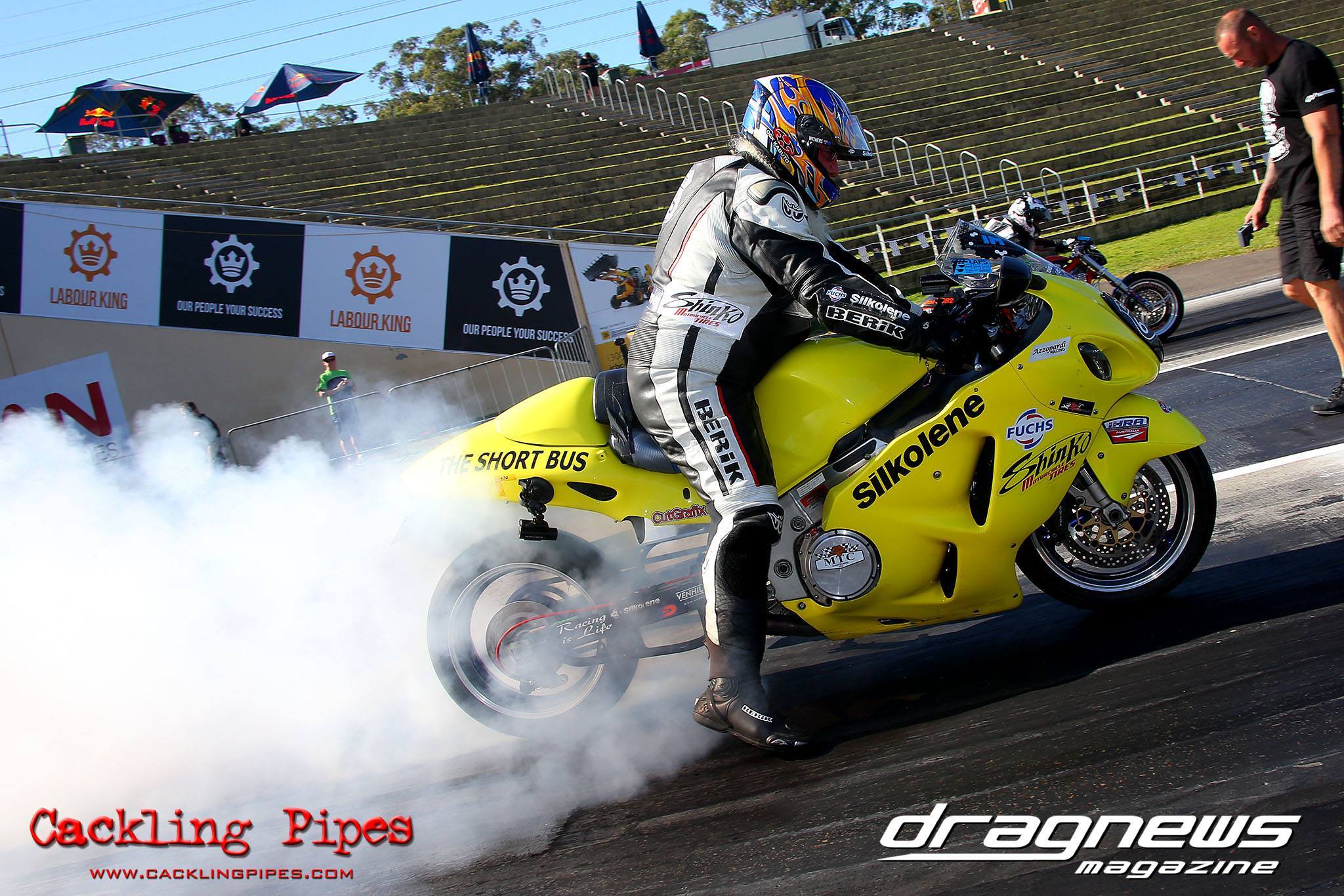
Image: Grant Stephens, CacklingPipes.com
Nothing else has been changed except for leaving the line at WOT, the weights on the throwout arms, spring tension and the two-step rpm to achieve consistent, repeatable short times and improving PBs.
It’s not a cheap exercise but if you’re chasing repeatability and consistency, my results prove what you can expect. If you want to know more, ask me a question and I’ll give you an honest answer.

THANK YOU TO THE FOLLOWING PEOPLE
Eric and Kevin, MTC Engineering; Leonard and Deanne, Azzopardi Racing; Ken Peatey, Rascal Race Engines; Scott, Rapid Motion; John and Deidre, Warrian Enterprises; Dave, Sydney Dyno; All at Kenma; Ken and Mary, Racing is Life; Rod, CutGrafix; Nick, Teknik Racing; Chris, Moto National; Terry, IM Composite Technologies; Aaron, Earmold Australia; Graham, Australian Moto Gear; Will and all from Bastards’ Corner.
WHAT’D IT ALL COST?
The final price depends on the exchange rate of the Australian peso on the day you do the deal. If you allow $3000, that’ll get you a complete ready-to-run MTC Slider clutch with a set of plates. That price includes freight, GST and all customs clearances.
If you need a clutch cover, I’d recommend the Australian-made LAE Quick Access cover, which is $310. Sending your cover to the US is an option but the local job is better.
WHERE’D YA GET IT?
MTC Slider Clutch. Supplied by Rapid Motion, Brisbane, Australia. Phone: 0412 907 924
LAE Quick Access clutch cover. Supplied by Dragbike Parts Australia. Phone: 0404 147 095
You Might Also Like


November 25, 2017
So quick access cover, bought separately… no picture of inside of cover lid. I see no provision to stop the clutch outer basket from pulling itself off the backing rivets, since the inner basket has its backing still on, all worse if you were to pull in a clutch lever/hand slider option…
I’ve been testing this idea and have one on GSX1400 with clear cover… and can see what happens next. I did fix one that had pulled off its rivets back before I retired to do my stuff, and it made me ask why…
November 3, 2022
Hi, I’m Norman from New Zealand. I have a 2007 Triumph Rocket 3 Classic that I’ve just recently lost all my gears. I new several months ago it was gonna happen. I was told you make high performance motorcycle clutch plates, could I have a price of a set with the shipping price please.