Yamaha's Y-Shop offers a great set of very reasonably priced LED Blinkers, making for a great DIY job that only requires basic tools and know-how.
I’ll be honest, I don’t mind getting the tools out to do some work on my own bike, it’s part therapeutic, part being cheap and, normally pretty rewarding. When it comes to electrics however… having had past issues on a second hand machine, it’s an area I approach with apprehension. I needn’t have worried with these Yamaha LED Blinkers (indicators) though.
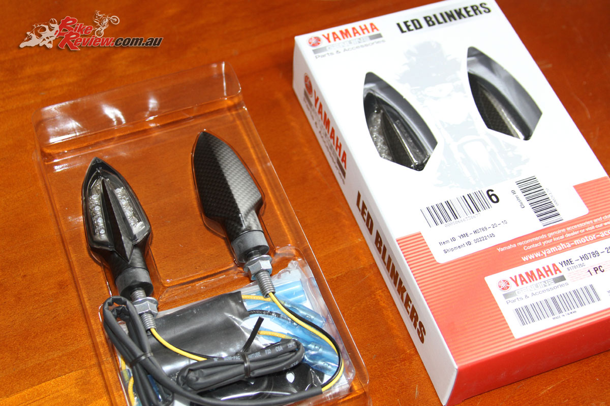
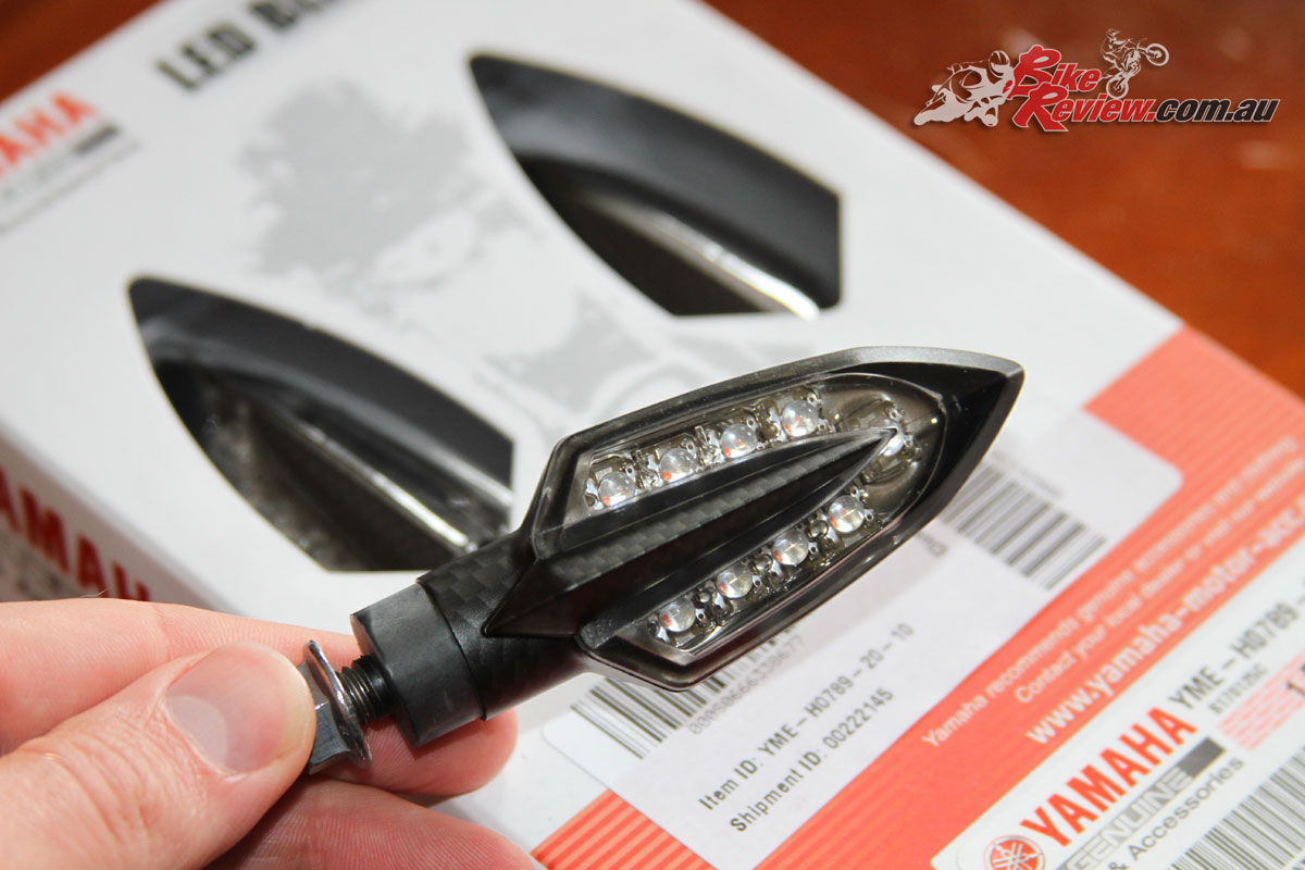
Yamaha’s LED Blinkers for the MT-07 Tracer
First up they come in a neat carbon-fibre-look finish (Black and Chrome also available), second they aren’t tiny and offer good visibility, and lastly and possibly most importantly, they come with the necessary resistors (rather than a LED relay). For a tad over $95 a set ($95.32 to be exact), that’s pretty exceptional value if you ask me. Just note you’ll need two sets, one front, one rear.

High build quality and well waterproofed resistors are the first thing I noticed out of the box.
I would never, ever, buy a set of ‘eBay special’ indicators, we’ve all seen the cheap integrated or tiny indicators which are barely visible at night, let alone during the day. If there was a special option that beamed the fact I was going to turn into other road user’s brain directly, I’d go for that, as it stands I’ll take the Yamaha option. Oh and I purchased two sets for my own non-Yamaha everyday ride following this install.
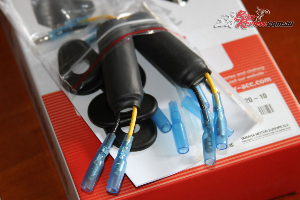
Resistors with bullet type connectors and waterproof sleeves
With a set to try on our Long Term MT-07 Tracer we opted to fit them to the rear of the bike, to see how they went. The kit includes the indicators themselves, a fitted nut on each, two spacers, some cable ties, a resistor for each side, and the fittings that you’ll need to put onto the standard wiring harness to replace the fancy plugs that Yamaha used.
It’d be kind of cool if it had matching plugs to the standard system, I’ll admit, and be truly plug and play, but I’m guessing the resistor couldn’t be sourced in this manner, and I’m not sure there’s the wire length on the resistor itself for a conversion. For the price and overall ease of install, it’s still a good option.

The only specialised tool I’d recommend is a multi-way Crimping Plier tool, they are about $20 at Bunnings or cheaper at Jaycar, and will help with stripping the wire to add new adapters, as well as crimping those new adapters on. You can do it manually with pliers, a sharp blade and regular or needle nose pliers, but it’ll be fiddly. We found the needle-nose pliers were useful even with the crimping tool.
Apart from that, it’s just the regular tools to pull apart the fender and disconnected it from the tail. We looked at trying to keep it all together and just feed the wires through, but it ended up being easier to detach the fender.
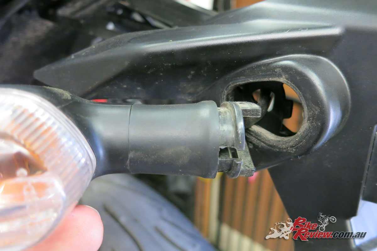
Pull the collar off the inside and the indicators will come straight out – keep in mind they are still plugged in!
The regular indicators are held in by a simple collar, remove that and they slip out. Pull the seat off and remove the cable ties and single connector which bundle and hold down the indicator, taillight and licence plate light wires. Disconnect just the indicators and pull the plugs and wires all the way through.
We disconnected the fender to make it easier to run the wires up through the it, with a piece of plastic that slots out, making it a breeze once removed. We’ll give it a clean later! Don’t lose the bolt spacers during this step.
With the new LED indicators you’ll need to take the nut off (pull one connector through at a time), and then put the two spacers on. The instructions said to place the outside spacer plate the opposite way we ended up doing it. We did it this way as it fit into the space properly and just made more sense.
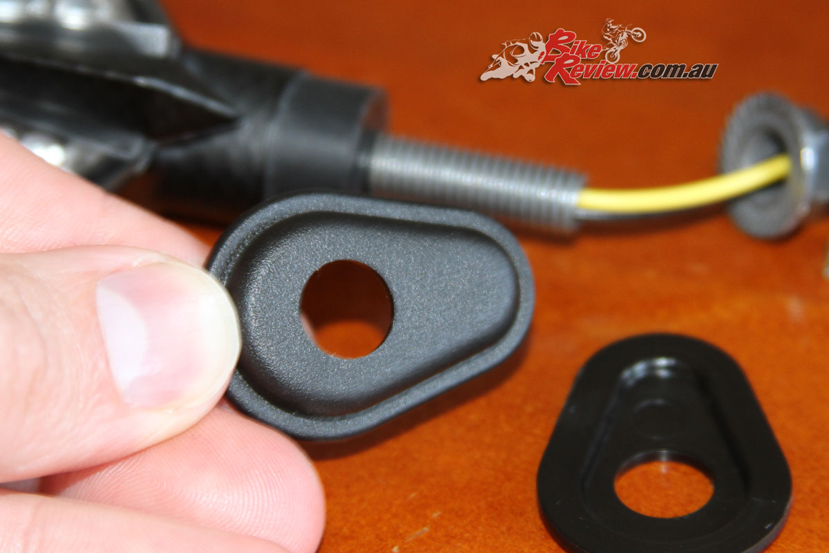
You can see the mounting ‘plates’ needs to be between the nut and the indicator.
Make sure they are facing the right way for installation, before putting the nut back on, then align them on the bike. The way we placed the plates their contour fills the original mounting point, and the second plate on the inside is tightened onto it with the nut. After a bit of head scratching I realised it would have been easier to have the contoured plate on the inside, but at that point it was all back on, and this keeps the indicators lower profile, which is a plus.
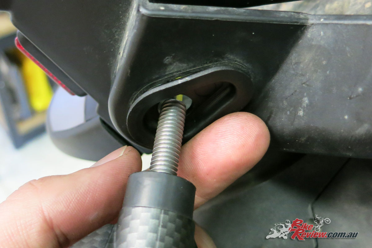
Here’s the orientation we used.
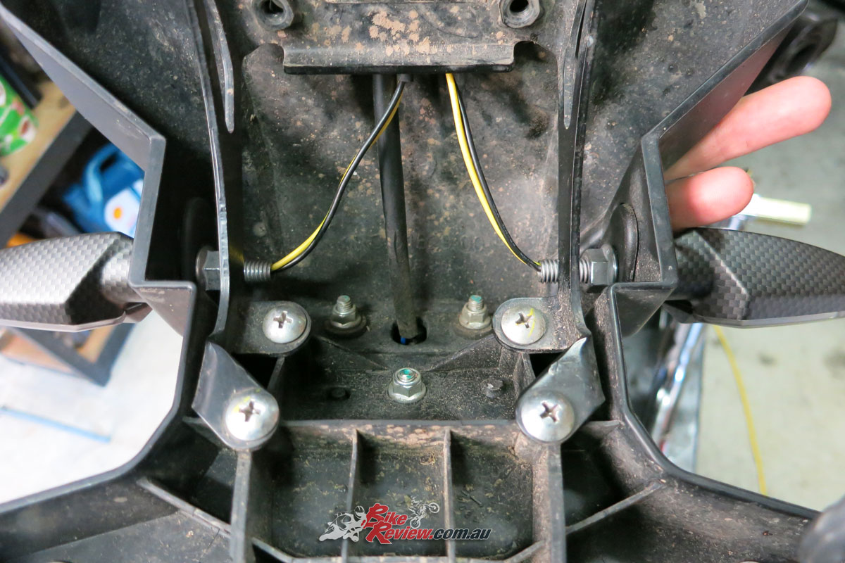
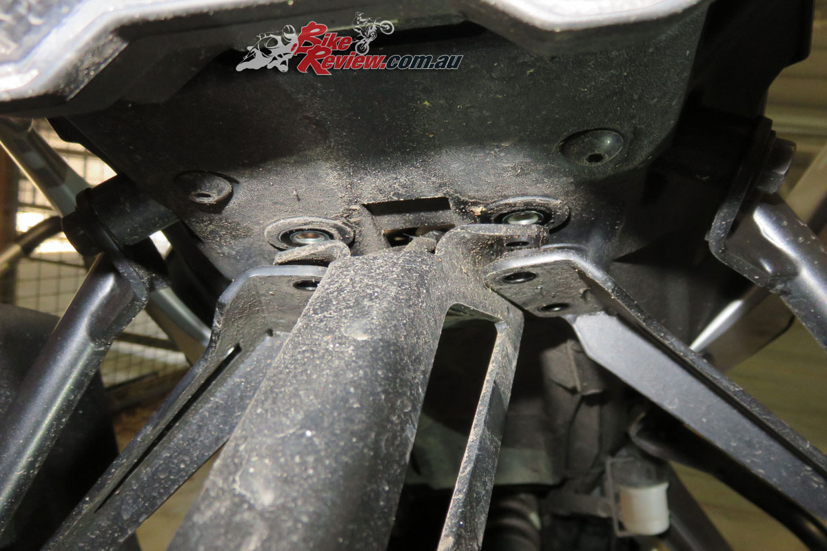
Inside shot of the inside plate and the nut, which pinches the two plates together.
Just replace the fender once you’ve completed this part, and make sure it’s all secured properly, and that any of the pannier frame bolts you’ve loosened are re-tightened.
Now in under the seat you’ll need to replace each of the standard plugs with two of the bullet type connectors provided. This is the fiddly part.
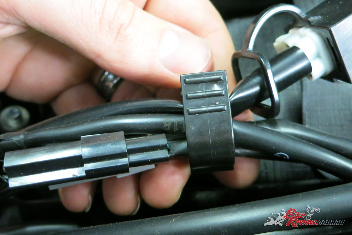
Under the seat remove the cable ties and clip that holds all the wiring together. You just need the two indicator sets.
Cut off the old plugs and keep them somewhere safe, they may come in handy one day. Trim the wire back so there’ll be a good contact area when you crimp the connector closed on the wire.
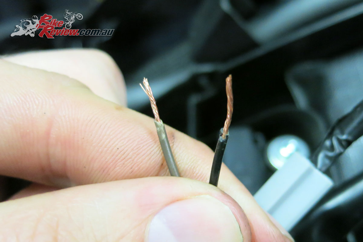
Wires trimmed back ready for the new bullet connectors.
We doubled the wire back on itself in order to ensure there was plenty of surface areas, then used the crimps to close the connector. Then we used the needle nose pliers to make sure it was really securely crimped together.
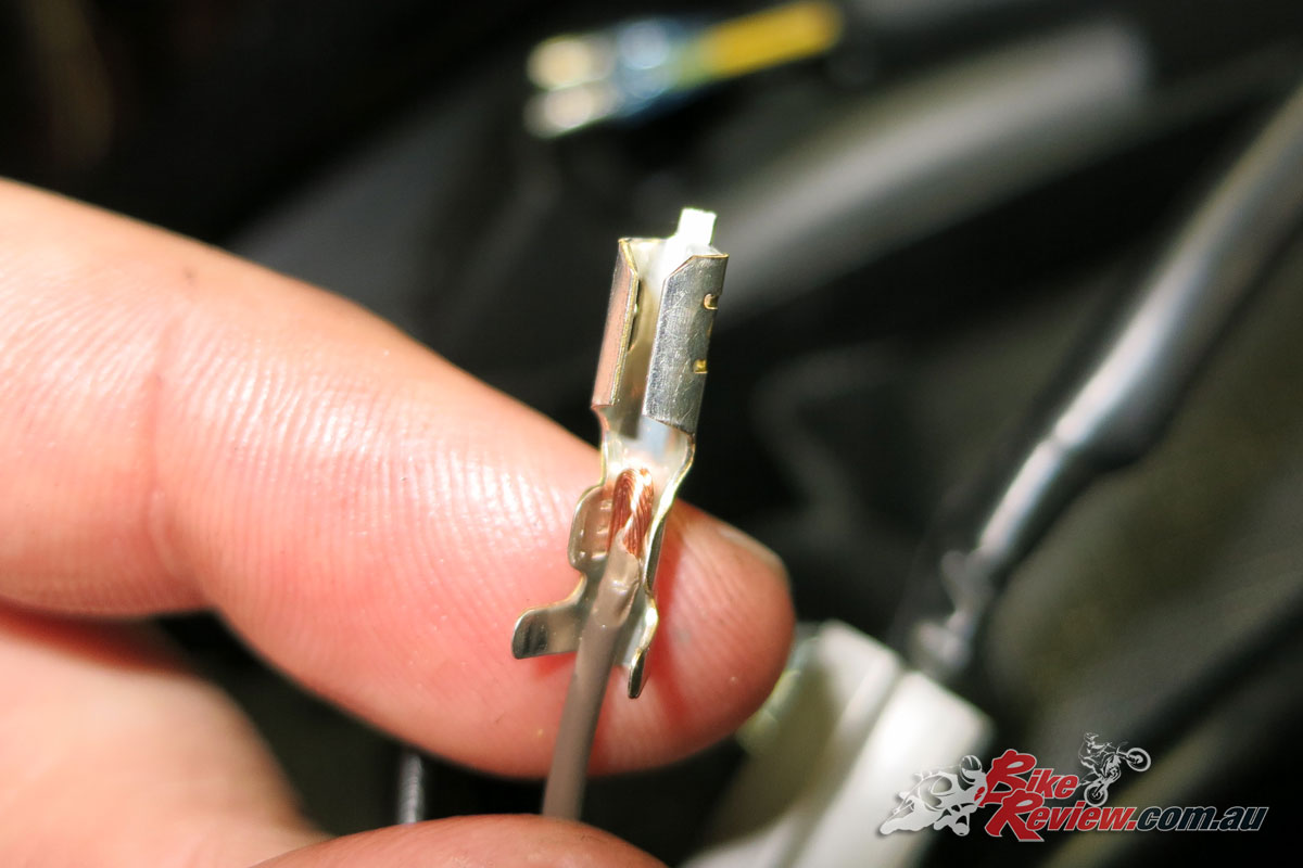
Get the wire into the right place, double it over for a better connection, then crimp.
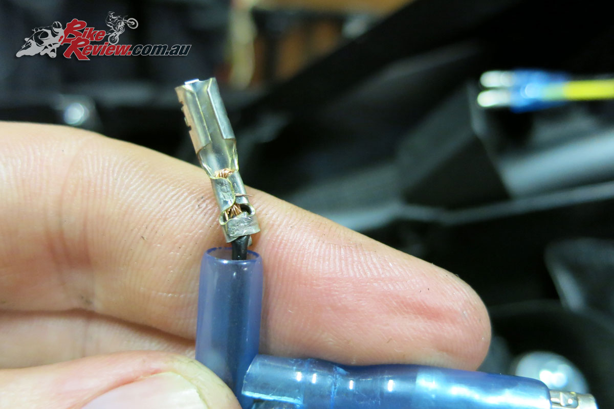
All crimped up and ready to go.
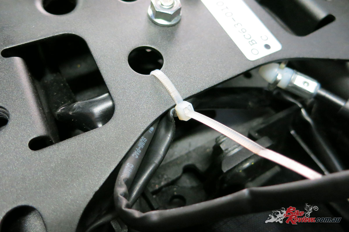
Now plug in the resistor, find somewhere good to place and cable tie them down, the instructions recommend on the frame, as they get hit and this will help dissipate the heat. We wanted to fit both as pictured by the standard wires aren’t quite long enough to do so. So one went here and the other was cable tied alongside the rear subframe near it.
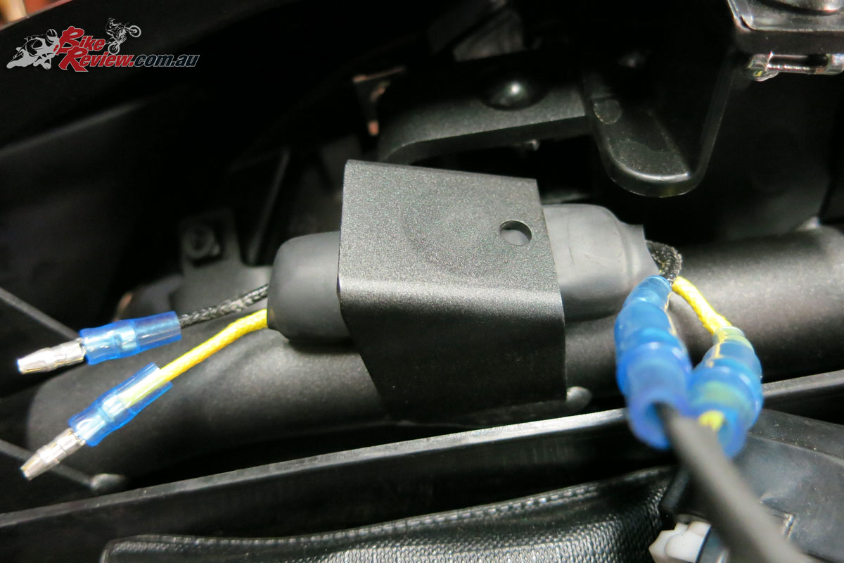
Here’s where we’ve placed one resistor, the other couldn’t be on the opposite side, due to cable length. Instead we cable tied it to the subframe.
Make sure when you’re plugging everything in that you connect black to black, colour to colour (grey to yellow/yellow to yellow). And just make sure you’ve got the right indicators activating before you close everything up. I’d recommend holding the bullet connectors together, make sure they are working, then push them together, as they’ll be hard to pull apart and you can start pulling the wires you just crimped out. Also make sure the waterproofing encasing is covering the connections.
Now just make sure you’ve got the indicators connected to the right side and cable tie the wires back into the original positions and add the clip back on which holds them together.
If you do need to pull the connections apart for any reason, use needle nose pliers on each, and hold them at the bases, where they crimp the wires when pulling them apart.
Now you should have super bright indicators fitted and working, and you can just replace the seat and go for a test ride.
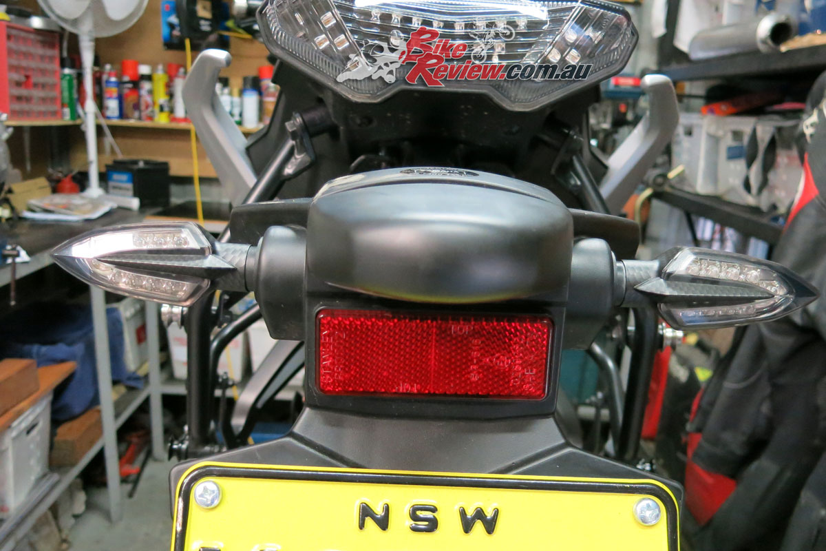
The end result, much cooler looking than standard, nice and bright, and an easy DIY job.
Like I said, I’m really impressed with these indicators and that’s why I bought them for my own bike.
You can check out everything we’ve done to the Yamaha MT-07 Tracer here, otherwise head to the Yamaha Y-Shop website to check out what you can get from your local dealer.
The Verdict | Staff Bike: Yamaha MT-07 Tracer LED indicator install
Awesome value
You Might Also Like