
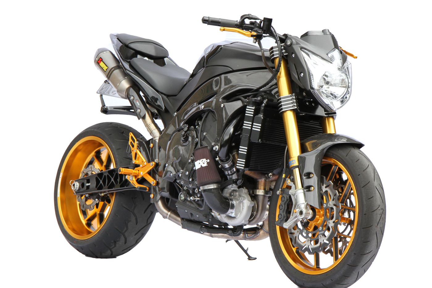
Before we go anywhere near tuning a turbo-charged engine we need to look at the setup of the turbo and how we will get a boost reading. Words: Wayne MacDonald Images: Wayne MacDonald, Heather Ware
Ever wondered what goes into turbocharging a motorcycle? Here’s a run down of the process and many variables for a turbo install.
 Turbo Size
Smaller turbo’s (such as a Garrett GT15) will have boost come on very early but will limit the peak horsepower. On a road bike this will remove the lag commonly associated with turbocharged vehicles.
However, you will need to be aware that the cam timing required to use a small turbo will be different to that of a larger turbo.
The explanation for this is the pressure difference between the plenum pressure and the exhaust manifold pressure. With a small turbo the pressure in the exhaust manifold may be between two and three times the pressure in the plenum. If you have conventional cam timing, your cams will most likely have 30 to 40 degrees of overlap (when exhaust valve and inlet valves are both open).
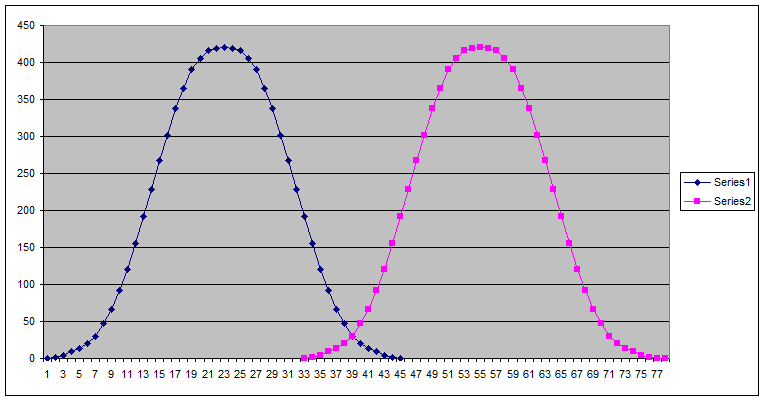
See the graph of cam lift vs. crank duration. The blue line is the exhaust cam and the pink is the inlet cam.
If you have twice the pressure in the exhaust manifold, the valve overlap will allow exhaust gas to move up into the intake manifold. The pressure difference will increase with revs and this will make the power fall off quickly as the revs increase.
A reduction in valve overlap by an adjustment in cam timing will ensure that the exhaust valve is closed, or very close to closed, before the inlet valve opens.
By reducing the valve overlap you will not get the “scavenging effect” from the exhaust. In a turbo application you will only get a “scavenging” effect at low revs when the pressure in the exhaust manifold is low.
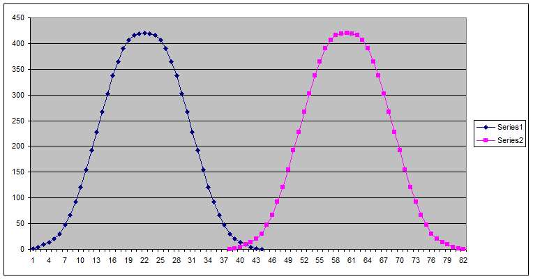
Illustration: The cam timing modified for a turbo application.
In addition, the change in cam timing also helps reduce the cranking pressure and effective compression ratio. This is due to the inlet valve closing further after bottom dead centre as it is after the valve closes that compressing of the mixture starts. This change to cam timing also helps reduce detonation because of the reduced cranking pressure.
If you are running a small amount of boost, this will allow you to run the motor safely without needing to go to the expense of dropping the compression ratio. Decompressing the motor allows more boost but it increases turbo lag because it makes the combustion process less effective (giving a smaller bang because the fuel air mix has not been compressed as much).
This in turn reduces the volume of exhaust gas produced, and it is the amount of exhaust gas that passes through the turbo that spins it to make the boost.
Air Temperature and Pressure Sensor Placement
When a turbo system is providing boost it is effectively like raising the atmospheric pressure. The best place to take boost pressure from is the plenum, not below the throttle plates. Taking the pressure reading below the throttle plates would make the bike run lean when the turbo is providing boost but the boost does not exceed the normal barometric pressure.
For example, if the throttle is at 20 per cent the pressure under the plate may be 0.5 bar. If the turbo is providing extra pressure in the plenum the pressure may be 0.7 bar at the same throttle point. If your pressure sensor is below the throttle plate you will not know that the pressure difference is due to boost and the ECU will only deliver the fuel required for 0.5 bar. This causes a lean condition.
The down side of having the pressure sensor read off the plenum is that the mixture will become rich for a short time when the throttle is closed. This, however, is much better than it getting lean. A good blow off valve will reduce the pressure in the plenum very quickly when the throttle is closed, and most modern engine management systems (ECU’s) do fuel cut on deceleration so the extra pressure will have no effect.
You can also put negative fuel trims in the throttle position mapping at zero throttle (but not if the system is using manifold pressure for low throttle mapping). Most modern motorcycles use manifold pressure-based mapping for low throttle fuelling, then switch to throttle position mapping once the throttle goes past 5 to 10 per cent throttle.
Once past the switchover point, the EFI computer will deliver fuel based on throttle position and RPM, and correct for barometric pressure. The MAP sensor should be disabled if possible as this adds another dimension to the tuning process that will do your head in! If the MAP sensor is still connected you also need to prevent it seeing the boost pressure as this could damage the sensor and will almost certainly cause the ECU to show a fault.
If the standard air temperature sensor is fitted inside the airbox this should be relocated. Don’t put it in the plenum as this will make the motor very hard to start when hot. This is because the plenum acts like a big heat sink and on hot starts the ECU will think the air temperature is very high. Most engine management systems use a high-pass filter on the air temperature sensor values. This means ECU will still think the air temperature is high well after the temperature inside the plenum has dropped.
Fuel Management
If the standard ECU can be flashed to accept a boost pressure input, this will provide a better result than a piggyback (add-on) system. The ECU has access to barometric pressure as well as boost pressure and can provide extra fuel based on the percentage differences between barometric pressure and boost pressure.
For example:
If pressure in the plenum is 1.2 bar and barometric pressure is 1.0 bar the percentage boost is 20 per cent.
If pressure in the plenum is 1.2 bar and barometric pressure is 0.9 bar the percentage boost is 33 per cent.
If you use a piggyback computer that only sees the pressure in the plenum, you will end up with mapping that changes from rich to lean depending on barometric pressure. This is not a major problem if all your riding is done in an area without noticeable altitude variations, as the barometric pressure fluctuations will not be very large. On the other hand, if you do ride in a mountainous area you will get large changes in barometric pressure because of the changes in altitude.
Mapping
Fitting a turbo manifold and plenum to a motor changes the tuned length of the exhaust headers and intake resonance. Because of this it is always good to do the first part of the mapping with the intake system set up to prevent any boost pressure building.
Simply leaving the charge tube hose loose will allow it to push away from the charge tube as soon as any pressure starts to build. This allows you to tune throttle position vs. RPM to match the new requirements of the motor before you try to map for boost.
Following this step first will make the boost mapping much simpler and should make the boost trims very linear to the boost pressure. If you try to map the boost side without first mapping for the differences in air flow off boost, you will have very unpredictable results as you will not know if the adjustments needed are due to changes in intake characteristics or changes in air pressure.
This part of the mapping does not need to be done over the entire throttle range. In fact you will run the risk of over-speeding the turbo if you try to do full throttle runs with no boost pressure. It will suffice to map the throttle side up to 40 per cent throttle as the low throttle area is the part of the map that is going to have to run nicely with and without boost pressure.
Low throttle mapping is best done with slow ramp rates on a dyno. This best reflects the conditions the motor will see in the real world.
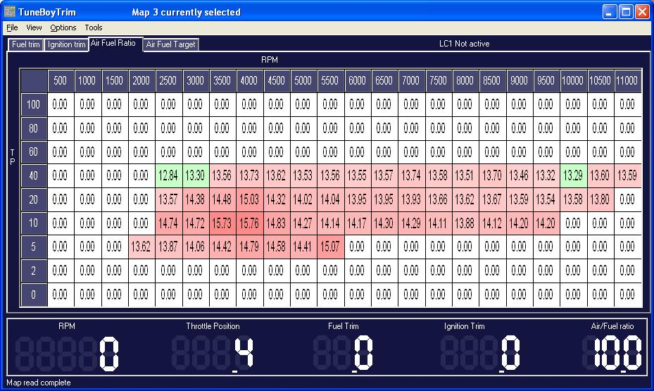
Illustration: Measured the Air/Fuel ratio for the throttle based mapping up to 40 per cent.
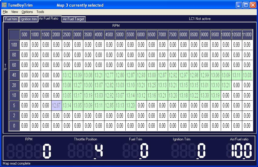
Illustration: The same area after the throttle vs. RPM trims have been corrected (no boost on the system).
The only area where you are likely to have large throttle openings without boost is low in the rev range. If you are mapping on a dyno with good load-hold ability you can set the dyno to hold an RPM and quickly turn to full throttle, then off again. Take note of the Air Fuel (A/F) ratio and adjust the throttle vs. RPM map to make sure the mixture is not lean.
Sudden throttle changes like this should show an A/F ratio of 11/1 to 12/1 because of the throttle enrichment function in the ECU. Once the throttle position-based mapping has been done you can connect the charge tube again and prepare to do the mapping for boost.
Boost Mapping
Don’t be tempted to increase boost to try and get big horsepower numbers. Many motors have been destroyed by increasing the boost past the point that is safe for the components in the motor. If the motor is standard you should not go past 0.4 – 0.5 bar.
Don’t expect your motor to defy the laws of physics and make more power increase than the boost per cent increase. If the motor makes 100 hp without the turbo, and you add a turbo system that adds 0.5 bar, this means the motor is getting 1.5 times the air that it got without the turbo. Don’t expect to get the full 50 per cent increase in power as the air will be heated as it is compressed by the turbo, reducing its density. In reality you would be lucky to get much more than a 40 per cent increase due to this heating of the air.
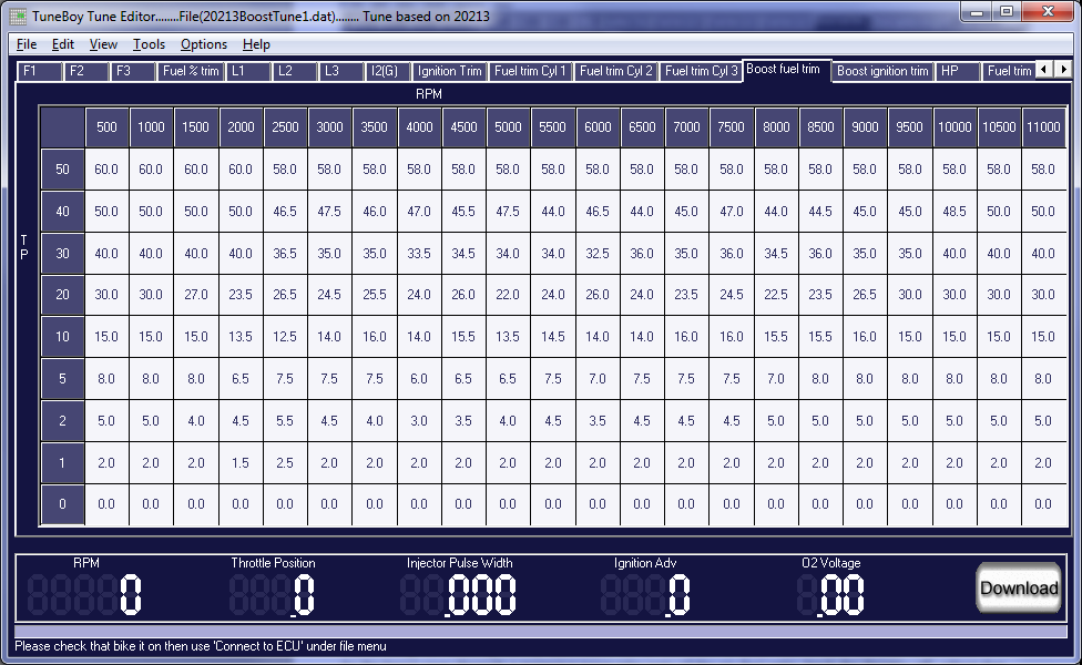
Always start on the rich side with boost fuel trims. Because you have tuned the system for no boost, the trims required for boost should be close to the per cent of extra air pressure. Start with a table that is at least 10 per cent richer from the onset.
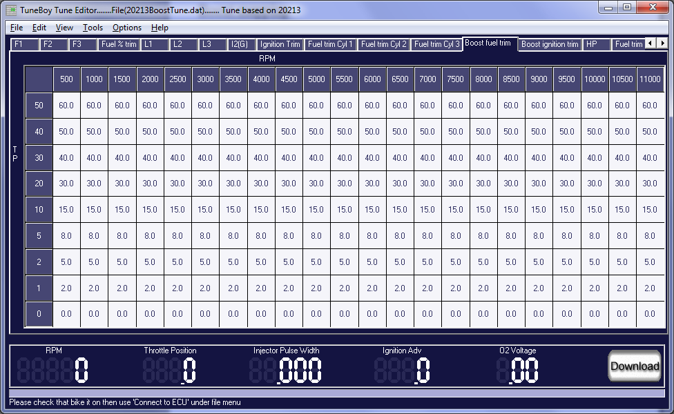
Illustration: The trims I start with on the boost side.
If the engine management system has a table for ignition retard under boost, you should take five to six degrees of ignition advance out of the higher boost area (20 per cent up) from mid RPM to high revs. If the tuning system you are using does not have boost ignition trims, you should take some ignition out of the higher throttle range from mid RPM upward.
It is much easier to add the ignition timing back later than it is to replace the melted metal to the piston. ALWAYS err on the side of safety when mapping a turbo.
Start tuning the low boost area first. It is tempting to do just one full throttle run to see what peak power it makes. Don’t do this as it is much easier to catch any potential problems at lower throttle positions. Start the boost mapping by setting the dyno to hold RPM then gently apply some throttle until boost starts to build.
Try to bring the boost up slowly and watch the A/F ratio to make sure it does not start to lean out. As the boost goes through a mapping point take note of the A/F ratio, back the throttle off, adjust that point in the map, then rinse and repeat. I follow this procedure up to the 30 per cent boost point then move to the next RPM point.
Once you have completed the mapping up to 30 per cent you should look at the trends in the trim values and extend these through to the higher boost levels. Make sure the values you put in at the higher boost points are still running rich.
This allows you to build the trim numbers for the higher boost area before you actually run the bike at higher boost.
Tuning over 30 per cent should be done in roll-on mode on the dyno. You should not attempt to tune the higher boost area with the dyno holding the RPM as this places unnecessary load on the motor – it is also not what happens in the real world. The motor should be allowed to accelerate as it would when riding on the street.
When doing dyno runs at high throttle you need to pay close attention to the A/F ratios and engine temperature. It is under high load that any fuel system issues will show up. Fuel pressure may drop at high load if the fuel pump cannot supply enough flow to keep the pressure up.
You may also see a leaning-out if the injectors run out of duty time. To help keep the engine temperature down while tuning you should set the thermo fans so that they come on at around 85 deg C. If you cannot adjust the thermo fan value in the ECU you should look at hard-wiring it while on the dyno.
If you do not have the fan on early enough the engine temperature will rise quickly beyond the normal running temperature of the motorcycle. It is not good to tune the bike when the motor is running hot as this will increase the chance of detonation.
Ignition timing
The final step in tuning should be to add back some of the ignition that was taken out before mapping the fuel. I use a dual channel acoustic knock sensor when tuning turbo motors. This has two bolt-on knock sensors that are bolted to the head and the bottom end of the motor. The controller outputs the filtered signal from the knock sensors to a set of headphones. When the controller detects knock, this is heard in the headphones. With a system like this you can adjust the ignition without fear of melting pistons.
The approach to take with ignition is to retard first, dropping the power, then to add ignition back in until the power does not increase. The power will always plateau before you start to get detonation from excessive ignition advance.
Once this plateau is reached back off the ignition to the point that gave the best power with the least ignition advance. On some motors you will need to add ignition advance at low throttle and revs to compensate for less cylinder filling when the turbo intake system is restricting air into the motor.
Fuel trims after tuning:
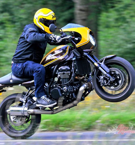
If the turbo is well sized for the bike you should have a machine that produces boost very low in the rev range.
My Triumph has done 70,000 km with the turbo fitted without a single problem. On it I reduced the rev limit from 10,500 down to 9,000 RPM as the power delivery in the midrange is more than adequate. Reducing the rev limit will also protect your motor.

Footnote:
In automotive usage, scavenging is the process of pushing exhausted gas-charge out of the cylinder and drawing in a fresh draught of air ready for the next cycle.
You Might Also Like


May 23, 2019
where can I see more photosof that bike ?
May 24, 2019
Check it out here:
https://bikereview.com.au/big-bang-turbo-power/